1. Size
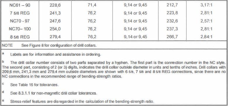
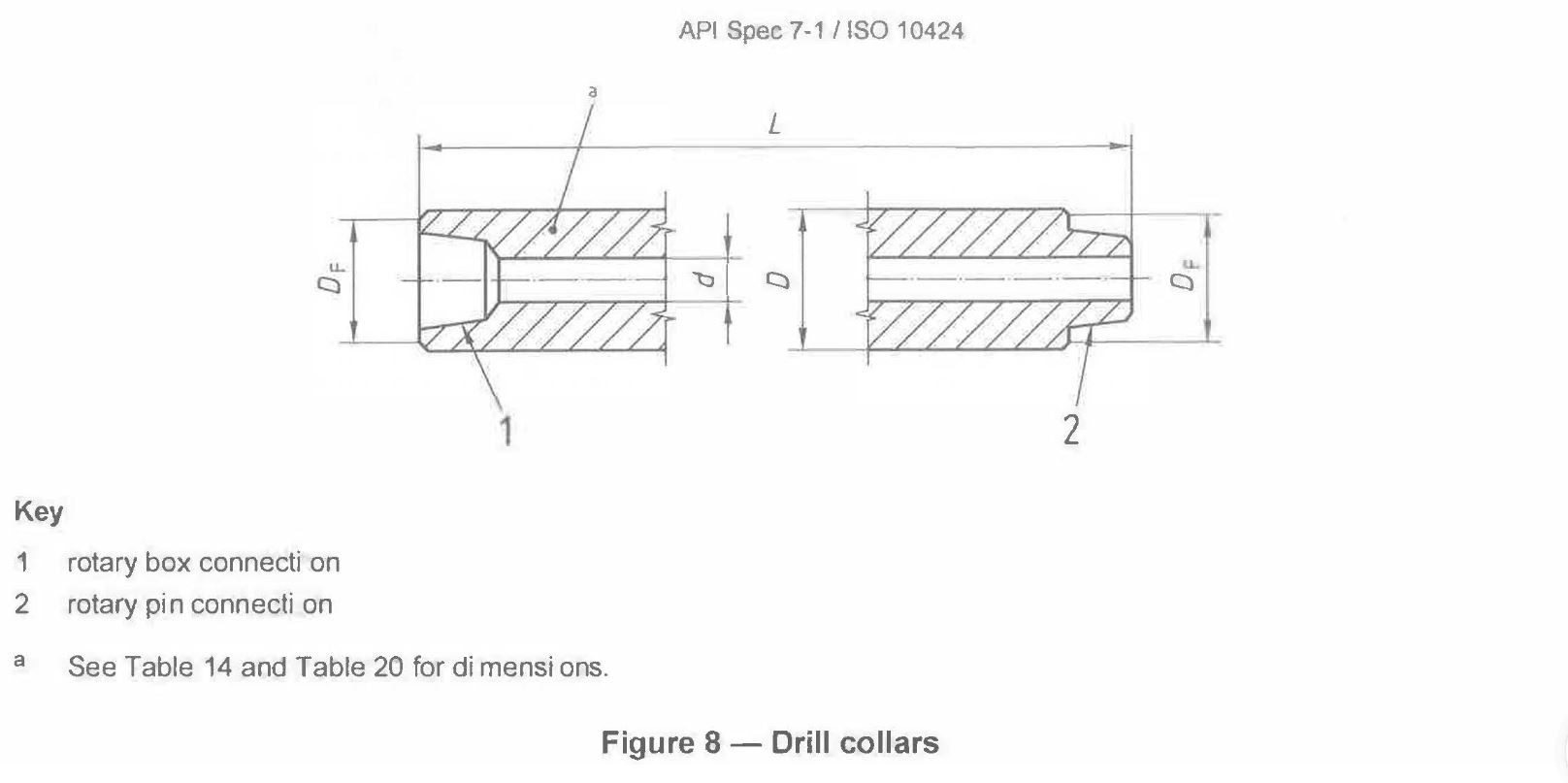
Standard steel drill collars shall be furnished in the sizes and dimensions shown in Table 14 and illustrated in Figure 8.

1.1 Outside diameter tolerances
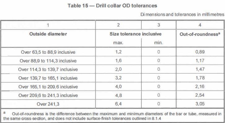
The outside diameter shall comply with the tolerances of Table 15.
1.2 Bores
All drill collar bores shall be gauged with a drift mandrel 3,05 m (10ft) long minimum. The drift mandrel shall have a minimum diameter equal to the bore diameter, d (see Table 14), minus 3,2 mm (1/8 in).
2. Surface finish
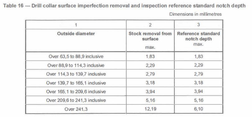
The minimum external surface finish shall be hot-rolled and mill-finished. Workmanship shall comply with ASTM A 434. Surface imperfection removal shall comply with Table 16.
3. Straightness
The external surface of drill collars shall not deviate from a straight line extending from end to end of the drill collar, when the straight line is placed adjacent to the surface, by more than 0,5 mm/m (1/160 in/ft) of drill collar length.
EXAMPLE On a drill collar of length 9,14 m (30ft), the maximum permitted deviation from a straight line is 9,14 × 0,5 = 4,6 mm (30 × 1/160 = 3/16 in).
4. Non-destructive examination
Each bar or tube used to manufacture drill collars shall be examined for both surface and internal defects in accordance with Clause 10 of this part of ISO 10424.
5. Connections
Standard steel drill collars shall be furnished with box-up and pin-down connections in the sizes and styles stipulated for the OD and ID combinations listed in Table 14. The connections shall conform to the dimensional and gauging requirements of API Spec 7.
5.1. Connection stress-relief features
Stress-relief features are optional. If stress-relief features are specified, they shall conform to the dimensions specified in API Spec 7.
The surfaces of stress-relief features shall be free of stress risers such as tool marks and steel stencil impressions.
Laboratory fatigue tests and tests under actual service conditions have demonstrated the beneficial effects of stress-relief contours at the pin shoulder and at the base of the box thread. It is recommended that, where fatigue failures at points of high stress are a problem, stress-relief features be provided.
The boreback design is the recommended relief feature for box connections. However, the box relief groove design has also been shown to provide beneficial effects. It may be used as an alternative to the boreback design.
Stress-relief features cause a slight reduction in the tensile strength of the pin and the section modulus of the connection. However, under most conditions this reduction in cross-sectional area is more than offset by the reduction in fatigue failures. If unusually high tensile loads are expected, calculations of the effect should be made.
5.2. Cold working of thread roots
Cold working of thread roots is optional. The method of cold working is at the discretion of the manufacturer.
As with stress-relief features, laboratory fatigue tests and tests under actual service conditions have demonstrated the beneficial effects of cold working the thread roots of rotary shouldered connections. It is recommended that, where fatigue failures at points of high stress are a problem, cold working be provided.
If threads are cold-worked, they shall be gauged to API Spec 7 requirements before cold working.
Gauge standoff will change after cold working of threads, and can result in connections that do not fall within the specified ISO gauge standoff if gauged after cold working. This does not affect the interchangeability of connections and improves connection performance. It is therefore permissible for a connection to be marked as complying with the requirements of API Spec 7 if it meets the standoff requirements before cold working. In such event, the connection shall also be stamped with a circle enclosing “CW” to indicate cold working after gauging.
The mark shall be located on the connection as follows:
a) pin connection: at the small end of the pin;
b) box connection: in the box counterbore.
5.3. Low torque feature
If the 8 5/8 Reg connection is machined on drill collars with OD larger than 266,7 mm (10 1/2 in), the faces and box counterbores shall conform to the dimensions for low torque feature as specified in API Spec 7.
5.4. Slip and elevator grooves
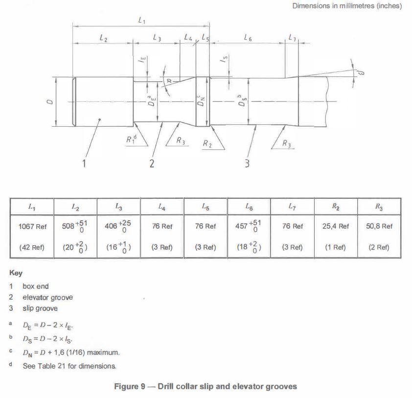
Slip and/or elevator grooves are optional. If they are specified, they shall conform to the dimensions shown in Table 21 and Figure 9. It is permissible to specify only the slip groove or only the elevator groove, rather than both. Location and dimensions of single features shall be in accordance with Figure 9.

5.5. Gall-resistant treatment of threads and sealing shoulders
A gall-resistant treatment of zinc or manganese phosphate shall be applied to the threads and sealing shoulders of all end connections of drill collars manufactured from standard steel. Application of the treatment shall be after completion of all gauging. The treatment type shall be at the discretion of the manufacturer.
Gall-resistant treatments are not readily available for non-magnetic drill collars, therefore are not required.


